At a glance
Calculate your print dimensions- All sizes in the test sheets include the four-module clear border on each side.
- The same total width can contain different module sizes when the payload or correction level changes.
- Our checks cover PDF geometry and ideal digital rasterization. Physical printing and phone scanning have not been tested.
What exactly are you measuring?
A module is one cell in the QR grid. The symbol is the grid itself; the quiet zone is the clear border around it. DENSO WAVE specifies a four-module quiet zone on all sides. Keep surrounding text, artwork, crop marks and borders outside that clear area.
Reserve space for both the symbol and quiet zone when you place the file. Cropping the white border to make a QR fit reduces the protected area even if the dark square appears unchanged. Use the final layout dimensions rather than the apparent size in a zoomed PDF preview.
Calculate the module size
Let N be the number of modules per side of the symbol, Q the quiet-zone width in modules on each side, and m the physical module width. With dimensions in millimeters:
Total width = (N + 2Q) × m
Module width = total width ÷ (N + 2Q)
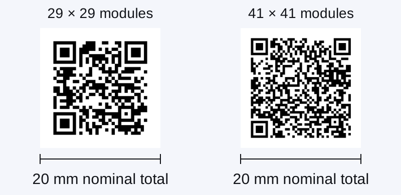
Our short URL uses M correction and a 29×29 symbol. With Q = 4, its full width spans 37 modules. The longer URL uses a 41×41 symbol and spans 49 modules including the same four-module border.
These are geometric calculations for two specific URLs, not measured scanning thresholds or recommended minimums. A different payload, correction level or border setting can change the numbers.
The short fixture stores https://scanfolk.com/standard. The longer fixture stores https://scanfolk.com/guides/qr-code-error-correction?example=print-size-density-comparison#damage-test. Both are public demonstration destinations; neither contains personal information or a Wi-Fi password.
Module dimensions in our two examples
| Total allocated width | Short example: 37 modules including border | Long example: 49 modules including border |
|---|---|---|
| 12 mm / 0.47 in | 0.324 mm per module | 0.245 mm per module |
| 16 mm / 0.63 in | 0.432 mm per module | 0.327 mm per module |
| 20 mm / 0.79 in | 0.541 mm per module | 0.408 mm per module |
| 25 mm / 0.98 in | 0.676 mm per module | 0.510 mm per module |
| 30 mm / 1.18 in | 0.811 mm per module | 0.612 mm per module |
| 40 mm / 1.57 in | 1.081 mm per module | 0.816 mm per module |
Choose candidates around the placement
Measure the likely scanning distance rather than assuming that a single distance-to-width ratio will cover every phone and payload. If you change the content or correction level, check the resulting density again. Increasing H correction can add modules; it does not replace adequate physical module size.
Choose around your placement
| Placement | What to establish before choosing a width | What to test on the final sample |
|---|---|---|
| A card or handout held nearby | Available space including border; actual encoded content | Normal camera focus at the expected close distance, without relying on digital zoom |
| A tabletop sign or menu | Where the guest will hold the phone; table lighting and reflections | The actual reading position, glare and shadows |
| A poster or wall sign | The intended standing position and accessible approach | Recognition from the real distance and viewing angle; use more space when needed |
| A label on a curved object | Curvature, texture and placement of seams | The finished object, with the code undistorted and the border unobstructed |
| A laminated or glossy sign | Reflections under the installation lighting | The real surface and angle; a matte paper test alone does not qualify the laminated version |
Choose a file and place it at the intended size
Use SVG when your layout and print workflow preserves vectors. It allows the QR geometry to be placed at a physical width without relying on a small raster source. Use PNG when your workflow needs an image, and check its effective resolution at the placed dimensions. Neither format removes the need for a real print test.
For a raster image, the relationship is pixels = width in inches × image PPI. A 20 mm image at 300 PPI corresponds to about 236.2 pixels, so allocating 237 pixels rounds upward. This is a resolution calculation, not a QR scanning minimum. Avoid repeatedly resampling or stretching the exported file.
Image PPI and printer DPI describe different things: stored raster samples versus printer dots. A PDF's physical dimensions are not guaranteed to survive a print dialog's Fit or Shrink option. Preserve the intended dimensions and verify the printed ruler.
DENSO WAVE discusses four or more printer dots per module for stable operation in its printer/scanner context. It also says that the scanner's reading limit matters. Treat those hardware considerations as reasons to test your setup, not as proof that a certain millimeter size works on all phone cameras.
Print a calibrated test sheet
Use the file matching the paper loaded in the printer:
Each is one page containing two payload densities at total widths of 12, 16, 20, 25, 30 and 40 mm. Square modules and finders, M correction and a four-module border are held constant. The figures are candidates for comparison, not pre-approved sizes.
Print at Actual size or 100%. Disable fitting, shrinking and borderless enlargement. Measure the 100 mm line or the 2-inch line on paper before evaluating the QR samples. If the ruler is wrong, record the measured length, correct the print settings and produce a new sheet. Do not label a scaled sample as a test of the stated width.
These sheets use vector geometry. Their screen preview does not represent physical life-size. The printed calibration line, not the browser zoom level, is the scale check.
Record recognition, decoded data and the action separately
Record the paper format, printer, print settings, measured ruler length, paper or coating, device model, OS, scanner and lighting. Start with the sheet flat, the camera facing it, normal camera zoom and measured lens-to-paper distances of 30 and 60 cm. Add the actual deployment distance when different.
For each condition, give the camera up to five seconds to offer an action. Record success or failure without silently retrying until it works. Additional attempts can be extra observations, with earlier failures retained. Do not fill in a device you did not use.
A recognized QR is not the same as a verified destination. Compare the complete decoded URL when your scanner exposes it; otherwise leave exact-data verification unconfirmed. Then follow the offered action and check that it opens the intended Standard page or guide. Classify connectivity or destination failures separately from inability to recognize the QR.
After the flat-paper comparison, test the chosen QR in its actual layout, at actual size, on the intended material. Repeat for other phone models or installation conditions you plan to describe. One working phone under one light does not establish a universal minimum.
What has been verified so far?
On October 15, 2026 we prepared the two calibrated vector sheets and checked their page dimensions, 100 mm and 2-inch line geometry. We rasterized every size and density at ideal 300 and 600 DPI, then decoded all 48 raster samples with ZXing-C++ 2.3.0. All 48 returned the exact intended URL; none returned a different QR payload.
This verifies the generated PDF geometry and digital rasterization under those conditions. It does not test a printer's scaling, ink spread, toner, paper, glare, physical camera or scanning distance. The physical test log is blank. No working or failing physical size is claimed.
Sources and review
Reviewed by the Scanfolk editorial team on October 15, 2026. Original vector sheets and calculations prepared October 15. The 48 exact decodes are ideal 300/600-DPI raster checks, not physical printer, phone or distance observations. No universal minimum or physically validated size is claimed.